The problem
The Neptune Apex is an amazing aquarium controller, but one of the few things it's missing, is a way to provide true moonlight simulation on anything bigger than a nano-tank. Sure, you can buy the LSM (Lunar Sim Module), but that provides you with 5 tiny little LED's. On a larger tank, they wouldn't even light up the rim of the tank.
I currently have 5 5W COB LED's over my tank for moonlight, driven by a MeanWell driver.

MeanWell drivers are great, because they provide what is called 3-in-1 dimming. You can dim them with either 0-10V, 0-10V PWM, or 0-100K Ohm resistance. For an Apex, they are ideal, because you can hook them directly to a VDM port, and dim them up and down as needed with no magic whatsoever.
The problem though, is the Apex has only partial moonlight simulation. It has a lunar table, which calculates what time the moonrise/moonset is on a given day. With this, you can setup your moonlights to come on at the correct time of day and period. However, it has no way to set the intensity of the moonlight. You can't say "on the full moon run at 100%, and on waxing crescent run at 45%". You can just turn them on or off.
What you need, is some kind of external control, that says, "today the moon is 40% of bright, so set the lights to 40%". Enter the ESP8266.

With this little microcontroller, an LED moonlight driven by a MeanWell driver, a free outlet on your EB8/EB832 for the driver power, and a few other parts, you can now have real moonlight on your aquarium.
How it works
The ESP8266 will connect to NTP to get the current date and time. From this, it will calculate the current lunar phase, and illumination level.
Once it has these, it will poll your Apex every 3 minutes for a VDM port you have configured with a ramp profile. This tells it the desired illumination. You setup your Apex with a few programs and profiles so it ramps the moonlight up from 0% to 100% over an hour or so, then runs at 100% for the majority of the moontime, then ramps back down from 100% to 0% to simulate moonset. Finally, your Apex will control the outlet that the driver is plugged into to turn it fully on or off.
So an example. Lets say it's now 30 minutes into moonrise, and the moon is 50% of full. Your ramp profile should currently have the VDM output at about 50%. The ESP has calculated the moon, and says that it is 50%. It then multiplies these two values, and sets the internal potentiometer to 25k Ohms, and your driver runs at 25%.
Parts list
- Wemos D1 Mini - https://www.amazon.com/Gumps-grocery-NodeMCU-ESP8266-Development/dp/B07ZZ5VTRB/ref=sr_1_9?dchild=1&keywords=wemos+d1+mini&qid=1609155485&sr=8-9
- 128x64 OLED Display (i2c) - https://www.amazon.com/gp/product/B076PNP2VD/ref=ppx_yo_dt_b_search_asin_title?ie=UTF8&psc=1
- Stripboard - https://www.amazon.com/gp/product/B019Q14GRQ/ref=ppx_yo_dt_b_search_asin_title?ie=UTF8&psc=1
- DFRobot Digital potentiometer 100k - https://www.dfrobot.com/product-1650.html
- 2 Position Screw terminal - https://www.amazon.com/DGZZI-50pcs-Terminal-Connector-Arduino/dp/B07SZFGH4B/ref=sr_1_10?dchild=1&keywords=screw+terminal&qid=1609156572&s=hi&sr=1-10
- Micro USB cable and wall wart, any will do.
You will need some basic soldering tools, little bits of wire, and a multimeter helps to test things, and a PC with the arduino IDE installed. https://www.arduino.cc/en/software
You will also need a Neptune Apex, a VDM module (an external one, not the one builtin to the unit), and an LED moonlight with MeanWell driver (with 3-in-1 dimming).
How to build
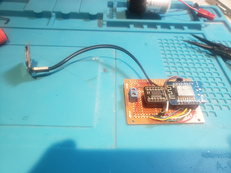
Take the perfboard, and on the side with the copper traces, use a knife or saw, and cut the traces down the middle of the board. You just need to break the strip-lines so the right half doesn't connect to the left half anymore. Use a multimeter to verify the traces are broken all the way down the board.
Use the headers supplied with the ESP and the digital pot to mount them to the board, so they straddle the cut line, with leads on either side. Make sure the ESP is mounted on the edge of the board, so the USB connector sticks out the back and you can power it up easily.
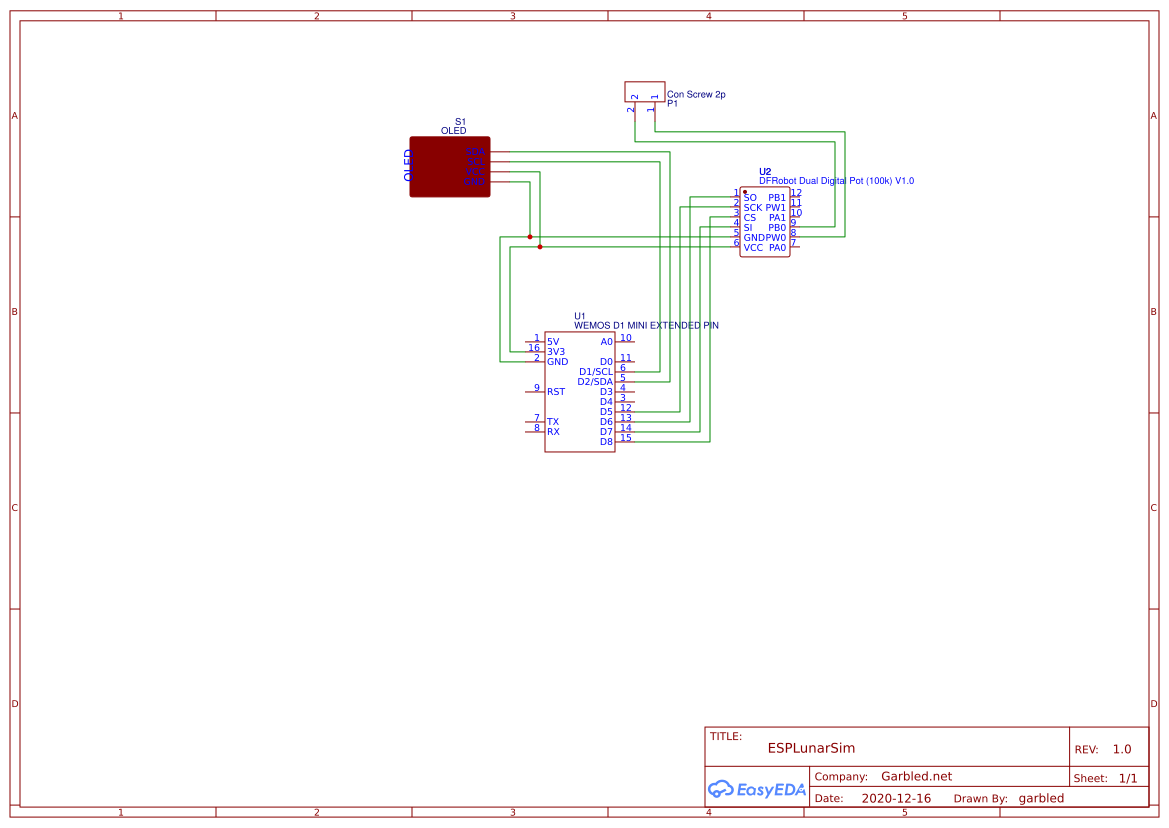
Follow the schematic to wire all the little connections to one another. It's actually pretty simple:
- 3v3 on the ESP goes to the OLED VCC and VCC on the digital pot.
- GND on the ESP goes to the OLED GND and GND on the digital pot.
- D1 on the ESP goes to SCL on the OLED.
- D2 on the ESP goes to SDA on the OLED.
- D5 on the ESP goes to SCK on the digital pot.
- D6 on the ESP goes to SO on the digital pot.
- D7 on the ESP goes to SI on the digital pot.
- D8 on the ESP goes to CS on the digital pot.
- PB0 on the digital pot goes to one of the pins of the wire terminal (doesn't matter which).
- PW0 on the digital pot goes to the other pin of the wire terminal.
You should probably double check your connections with the multimeter once it's all wired up. Just make sure your solder joints are all good and each connection goes where you think it does, and not somewhere else.
Now install the arduino IDE on your PC. You will also need to install the support for the ESP8266. These instructions will help: https://randomnerdtutorials.com/how-to-install-esp8266-board-arduino-ide/
You will need to go to the library manager of the arduino IDE, and install some libraries (Tools -> Manage Libraries):
- ESPAsyncWebServer https://github.com/me-no-dev/ESPAsyncWebServer
- ESPAsyncWiFiManager https://github.com/alanswx/ESPAsyncWiFiManager
- ESPDateTime https://github.com/mcxiaoke/ESPDateTime
- ESP8266_and_ESP32_OLED_driver_for_SSD1306_displays https://github.com/ThingPulse/esp8266-oled-ssd1306
- ArduinoJson (v6) https://arduinojson.org/?utm_source=meta&utm_medium=library.properties
- ESPAsyncTCP https://github.com/me-no-dev/ESPAsyncTCP
- AsyncHTTPRequest_Generic https://github.com/khoih-prog/AsyncHTTPRequest_Generic
If you can't find some of these in the library manager, simply download them from github into directories in your "libraries" directory of your arduino install.
Then download the code for the lunar simulator from my github: https://github.com/garbled1/ESP_Apex_LunarSim
You just need the .ino file.
Connect the ESP8266 to a USB port of your computer, start the IDE, open the .ino file, and go down to line 23 in the code. Change the APEX_HOST to the hostname or IP of your Apex on your local network. Also, change the NTP_SERVER on line 24 to another ntp server, like 0.debian.pool.ntp.org
Click verify to make sure everything compiles, and once it does, you can click upload to upload the code to your ESP. You can watch on the serial monitor to make sure everything is working correctly.
You should see it print the words "Initializing" on the display, and then switch to the normal display, which shows the current date and time, and the lunar phase and illumination.
Now you need to program the Apex.
Programming your Apex
A full set of profiles and outlet programming is available here: https://github.com/garbled1/ESP_Apex_LunarSim/blob/main/ApexProgram.md
Basically you need to do the following:
- Plug your MeanWell into an EB8/EB832 outlet, and program it to turn on and off with the If Moon statement.
- Build 3 ramp profiles, MoonRise, MoonSet, MoonOn, to ramp up/down the moon and set it to 100%.
- Build 3 virtual outlets, to control when the moonrise/set/on run.
- You need an UNUSED port on the VDM. Luckily, the VDM has a serial port, which most people do not use. You can use one of these, and still have the 4 normal VDM ports available for your use. I picked the BLU one from the serial. Program this with your ramp profiles.
Setting up the ESP
Once the ESP is powered up, it will need information to setup your wifi. Luckily, it creates a simple access point for you. You can scan for wifi connections with your phone, and find the ESP on your available connections. If you connect to it, it will display a simple little web page where you can configure it with your router and SSID details, as well as set some of the settings. Once you do so, it will disconnect from your phone, and connect to your local network.
Once it's up on your local network, you can enter it's IP into your browser to get a simple web page that shows the current moonlight, and lets you modify a few settings. There is also a link to an info page that gives more details about what is going on behind the scenes.

The settings you care about are:
- Apex hostname or IP: The hostname or IP address of your apex on the local network.
- Max illumination: A number between 0.0 and 1.0. If you want your moonlights to never run above say, 50% of full power, you could enter 0.5 here, and it will scale the calculations between 0-50% of the driver's maximum power.
- Minimum Pot Res: The minimum potentiometer resistance in kOhms. It defaults to 5, which is 5% of driver power. You can set this to whatever, and it is the lowest value the system will set for moonlight.
- Apex Moon Device: Case sensitive, the name of the VDM port you chose when setting up the Apex.
- Apex Poll in seconds: How often to check the Apex for updated data from the VDM port.
Finally, at the bottom of the info page, there are also instructions to upload new code to the device. If you want to make changes to the code, or fiddle with it, you can upload new code to it with the /update URL, without having to hook your PC up to it directly.
Final connections
Plug the ESP into a USB wall-wart with a micro-USB cable. Attach the two dimmer lines from the MeanWell into the terminal block on your circuit. It doesn't matter which wire goes where. At this point, everything should be working!

I made a little 3d-printed box for mine (which is just barely adequate, but, eh) and assembled it with some M2.5 screws I had lying about. It's not the perfect box, but you can download the STL from my github page.
And with this, let there be moonlight!